Return to previous page
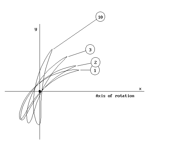
Figure 1 - Example of the use of program STACK for stacking blade sections of a fan.

The executable code STACK enables the student to generate blade geometry for up to ten sections from hub to casing of a turbomachine and to stack these in any desired manner. For example the sections may be stacked on their leading edge, trailing edge or centre of gravity, the latter being helpful for minimising centrifugal stresses in the case of a rotor.
STACK provides the facility to select base profile thickness, stagger, pitch/chord ratio and camber (circular arc or parabolic), and automatically constructs the consequent blade profiles. It then proceeds to calculate the area, C. of G., principal axes and second moments of area about the principal axes of the various sections which have been designed.
This facility enables the student therefore to take the blade designs from the other program CASCADE for a range of meridional sections and to stack these in a manner suitable for production of the complete blade envelope and ready for blade stress calculations. Typical applications would be for a compressor, fan or turbine blade. The figure above illustrates the stacking of four blade sections on their C. of G. during the design of a typical fan.
Return to previous page
Return to home page
