Quick Guide to ANSYS Workbench
(Mostly valid for v13.0 and later. Licensing seems to have been sorted out, which is a good thing, but we are still learning what the new issues are…)
The basic steps are covered in this document: QuickGuideTo-Ansys.pdf.
MEC3014 Coursework
Rob Davidson has now running this coursework – see Blackboard for latest instructions.
IMPORTANT: The official guideline is here below; Mr Davidson’s detailed guide may differ slightly.
Specification
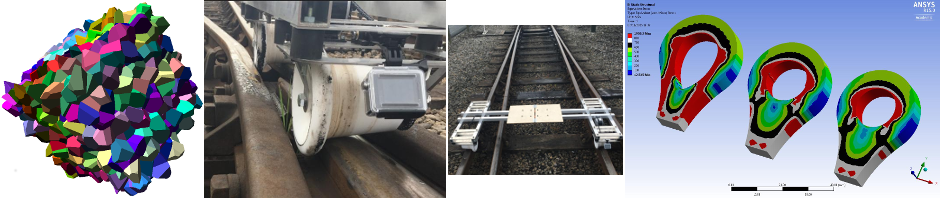
We will be laser-cutting a hook from 8mm-thick high-strength steel:
- The top hole has diameter 16mm.
- The seat at the bottom has diameter 30mm.
- The centre-centre distance is 160mm.
During testing the hook must meet the following specification:
- The hook must not yield before 30kN.
- The hook must yield by 60kN.
- The hook must fail by 90kN.
Design Notes
- Treat this as a two-dimensional design – do not chamfer or fillet the edges.
- Use only straight lines and circular arcs. Do not use ellipses or splines – the laser cutter will ignore these.
- The laser-cutter has 0.2mm precision – make allowance for this in your design.
- In Inventor, you can use Split Surface to split the hole at the top into an upper (load-bearing) and lower (free) surface.
Initial Submission – Final Hook Design
The final design will also need to be submitted electronically to Mr Davidson – please follow the instructions for this very carefully.
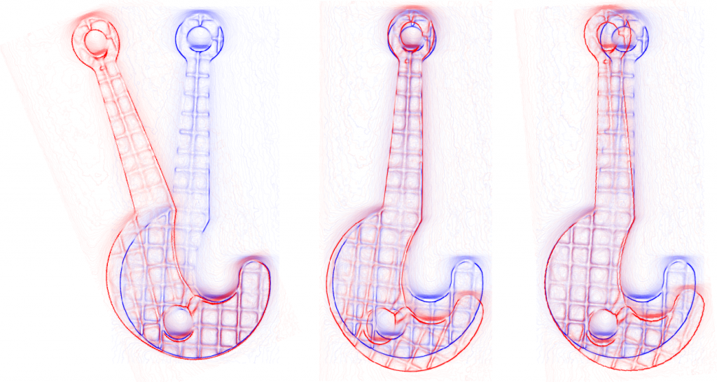
Overlaid images of a (not particularly good) hook before and after testing, showing clearly where the hook has deformed plastically.
Final Submission – Logbook
Submission Date: (To be confirmed – depends on date of hook tests.)
You must keep a logbook showing the development and analysis of your hook design.
For each design:
- Include screenshots of the hook in ANSYS showing equivalent (von Mises) stress. The colour bar must be included in the figure. Please adjust stress ranges and colours to be consistent across all designs and analyses, as far as possible.
- Make it clear what mesh you are using, and what constraints and loads are applied. If these are the same as in the previous design, then please say so.
It is good to see hand calculations in the logbook – where these are appropriate. For example, what is the mean stress across the neck near the top of the hook where bending stresses are low? Or you could treat the region around the top hole as a curved beam, or you could even approximate the section immediately to the right of the bottom seat as a curved beam. See, for example, this lecture note: Going Round the Bend.